ASTRA Controller Firmware Update via UART serial port
Serial Port Upgrade
Upgrade over the serial connection using a Serial-to-USB adapter: CH340, FTDI FT232, CP2102/2104, PL2303, etc.
Danger
Some adapters can be switched between 3.3V and 5V for the data pins, but still provide 5V on the power pin which will
irreparably destroy your device. You MUST ensure the data (RX and TX) and VCC pins are set for
3.3V. The minimal power supply from USB adapter requires at least
0.5A (ESP32 microcontroller consumption).
Hardware Preparation
- Disconnect the power supply from the ASTRA module
- Open the enclosure of the ASTRA module
- Locate the controller board in the top part of the enclosure
- Find the programming header on the board
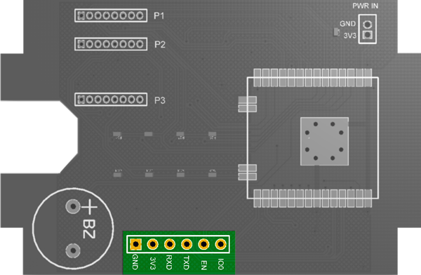
Wiring Connection
| Serial Adapter | ASTRA UART |
|---|---|
| 3V3 | 3V3 |
| TX | RX |
| RX | TX |
| GND | GND |
Flashing Tools
Choose one of the following tools:
- Tasmota Web Installer – Flash Tasmota using a Chrome-based browser for ESP82XX and ESP32
- ESP-Flasher – GUI flasher for Tasmota based on esptool.py for ESP82XX and ESP32 (Windows, Linux or Mac)
- Esptool.py – The official flashing tool from Espressif for ESP82XX and ESP32 (Requires Python)
Programming Mode
ASTRA module needs to be put into programming mode before the firmware can be uploaded:
- Connect the IO0 pin to GND
- Push the RESET button
- After 1-2 seconds, release the RESET button
- Disconnect the IO0 pin from GND
- Flashing process is now in progress
- After uploading firmware, push the RESET button
Success
Firmware update completed successfully!