ASTRA - Getting Started Guide
Controller Installation
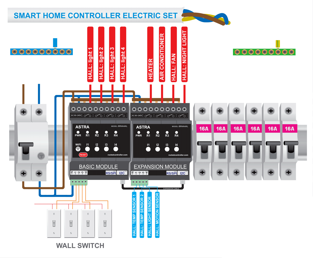
The ASTRA controller is designed for mounting in standard electrical enclosures on DIN rails. The device installs alongside circuit breakers (fuses). The controller's front panel matches standard protective cover window dimensions — after installation, all connected wires will be hidden while LED indicators and RESET button remain accessible.
Installation Sequence
1. Preparation
Remove the protective panel from the electrical enclosure to access the DIN rail.
2. Mechanical Mounting
Secure the controller onto the DIN rail. Ensure the latch is properly engaged.
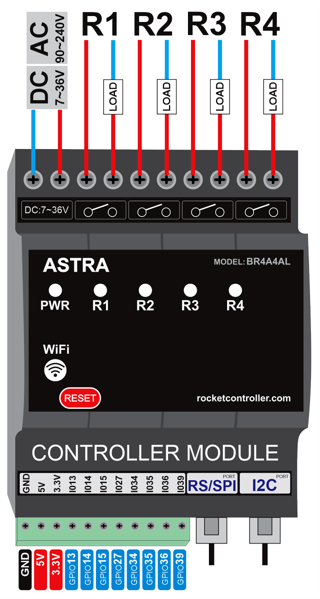
3. Power Connection
- Connect power through a circuit breaker up to 5A (controller consumes max 0.8A for 90~240VAC and 1A for 7~36VDC)
- Use power terminals according to housing markings
- Refer to the wiring diagram in appendix
Warning
Always disconnect power before performing installation work
4. Load Connection
Relay terminals: 3-4, 5-6, 7-8, 9-10
- First terminal of each pair — load power input (L)
- Second terminal — output to load
Danger
Maximum load per relay — 16A
5. Input Connections
The controller supports three types of input signals:
5.1 AC Inputs
- For connecting wall switches and toggle switches
- Terminal 1 — Neutral (N)
- Terminals 2-5 — Phase inputs from switches
- Operating voltage: 90-240VAC
5.2 DC Inputs
- Isolated dry contact inputs
- Operating voltage: 7-90VDC
- Terminal 1 — Common (-)
- Terminals 2-5 — Positive inputs (+)
- NPN discrete sensor support
5.3 GPIO Inputs (Direct Connection)
Direct access to ESP32 microcontroller:
- Power: GND, 5VDC (output), 3.3VDC (output)
- GPIO pins: 13, 14, 15, 27, 34, 35, 36, 39
Warning
GPIO logic level — 3.3V. Exceeding this may damage the controller!
Interface Description
6. Front Panel
- LED indicators: Display relay and input status
- RESET button: Hardware controller restart
7. RS/SPI Port (RJ Connector)
For external device connection:
- Interfaces: RS-232, RS-485, Modbus RTU
- Direct connection to ESP32 SPI bus
- Requires appropriate embedded module installation
8. I2C Port (RJ Connector)
- Expansion module connection
- Direct connection to ESP32 I2C bus
- Supports up to 127 devices on bus
9. UART Port (Internal)
How to connect USB-UART module to ASTRA controller See more
Note
Access requires opening the enclosure
Used for:
- Firmware updates
- Terminal debugging
- Recovery after failures